 Connecting multiple electronic devicesConnecting multiple electronic devices
|
Mode |
Tool |
Tool set |
|
Distributor
Schematic Distributor
|
Cable
|
Preview |
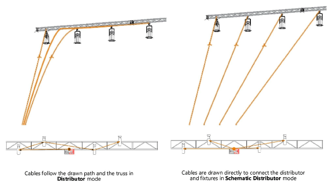
Distributor and Schematic Distributor modes both connect distributors to electronic devices. The first mode patches electronic devices to a distributor by creating cables that follow a drawn path. The second mode also connects distributors and electronic devices, but it draws the connection as a direct link, to clearly identify the devices plugged into the distributor.
The number of electronic devices that can be connected is equal to the number of outputs on the distributor.
To connect a distributor to multiple electronic devices:
1. Click the tool and mode.
2.Click Cable Style on the Tool bar to select a resource from the Resource Selector.
3.Click on the source distributor.
The Select Output dialog box opens. See Selecting the output. (If the option to select the next free output is selected, the dialog box does not open.)
4.Do one of the following:
● If a cable path exists, it is highlighted as the cursor moves over it. Click on the starting end of the cable path to create the new cable along the path. The cable run is created along the path, using the specified parts. At the end of the path, continue clicking to split off from the path and complete the cable run.
Schematic Distributor mode does not make use of a cable path, since it’s a schematic view.
● Click the appropriate mode in the Tool bar to select the creation method for the cable. For more information on the polyline tool modes, see Polylijnen tekenen.
5.Click to set the end of the segment and the beginning of the next, snapping to existing geometry; cables normally follow the truss system path as they are placed. As you place the cable, compatible objects such as distributors, electronic devices, other cables, and trusses are highlighted; click to connect (see Concept: Attaching loads to rigging objects). Click on the electronic devices to connect as you draw the path; the next sequential output is assigned. Continue drawing segments in this manner and double-click when complete.
A cable connects each output from the distributor to the electronic device, either following the path drawn in Distributor mode, or with a direct path in Schematic Distributor mode. Depending on the Cable Preferences, the connector cables can appear curved for easy identification.
~~~~~~~~~~~~~~~~~~~~~~~~~


