 Placing jackfields and linked jackfields
|
Tool |
Tool set |
|
Jackfield Linked Jackfield |
Schematics |
The tools place jackfields or linked jackfields, of the video, audio, optical, or data type.
![]()
Jackfield modes
![]()
Linked Jackfield modes
|
Mode |
Description |
|
Single Click
|
Places a single jack or linked jack at the click location |
|
Linear Array
|
Places an array of jacks or linked jacks along the drawn line |
|
Video Jack/ U-Linked Video Jack
|
Inserts a video jack or a U-linked video jack type of specialized device |
|
Audio Jack/Full-Normal Audio Jack/ Half-Normal Audio Jack
|
Inserts an audio jack or full or half normal audio jack |
|
Data Jack/Normal Data Jack
|
Inserts a data jack or normal data jack |
|
Optical Jack/Linked Optical Jack
|
Inserts an optical jack or linked optical jack |
|
Group |
Assigns the panel to a named group of jackfields. This extends the name space of large patching systems by adding a group prefix in front of the row/column value. |
|
Panel/Port |
The panel and port number are set according to the options in the ConnectCAD settings |
|
Preferences
|
Opens the Jackfield Preferences dialog box, for setting default values |
To insert a jackfield or linked jackfield:
Click the tool, and select the placement mode.
From the Tool bar, select the type of jack or linked jack to place by clicking the mode.
Click Preferences to open the Jackfield Preferences dialog box. Specify the default information for the devices to place.
Click to show/hide the parameters.Click to show/hide the parameters.
|
Parameter |
Description |
|
Connector Types |
Select the left and right connector type for the jack or linked jack. The list of available connectors displays according to priority (uncategorized, preferred, custom, workgroup, and default) and can be customized (see Specifying ConnectCAD settings). |
|
Manufacturer |
Enter the make and model of the device |
|
Device Defaults |
|
|
Height (RU) |
Select the height in rack units |
|
Height/Width/Depth |
Enter the device’s default dimensions |
|
Weight |
Enter the device’s default weight |
Specify the Group, Panel, and Port by selecting the values from the lists on the Tool bar. By default, the values from the ConnectCAD settings are applied (see Specifying ConnectCAD settings), but they can be overridden here.
If you continue placing the same jackfield device, these values automatically increment.
Click to place the jack or linked jack into the drawing. If placing the device into an existing circuit, the device splits the circuit.
In Single Click mode, click once to place the object.

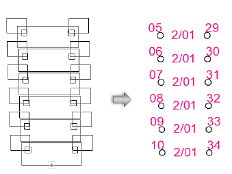
In Linear Array mode, click once to start the array; move the cursor to set the distance and direction of the linear array. Press the Shift key to constrain to the horizontal or vertical direction. The preview indicates the spacing and placement of the objects; the floating Data bar shows the Count. Click to place them.

The device can be edited later from the Object Info palette.
Click to show/hide the parameters.Click to show/hide the parameters.
|
Parameter |
Description |
|
General |
|
|
Device Name |
Displays the device name for use in reports; by default, a device prefix followed by the group and panel number displays |
|
Symbol |
Displays the symbol selected for the device label; select a different symbol definition from the list if desired. The options include different locations for the tag and description labels. |
|
Display Tag |
Enter the tag name (normally this is the group and panel number of the device) for display on the drawing |
|
Description |
Enter a description, such as the manufacturer and model name, for display on the drawing |
|
Manufacturer |
Enter the make and model for use in reports |
|
Save as Symbol |
Does not apply to jackfields or linked jackfields |
|
Save to Database |
Does not apply to jackfields or linked jackfields |
|
Physical |
Specify the dimensions of the device (height/width/depth), the power requirements in watts, the weight in kilograms, the height in rack units, and the rack width (for more information, see the Rack Width description in Placing equipment) |
|
Configuration |
Indicates that the device is a module that fits in a rack frame |
|
Number of slots |
For modular devices, enter the number of frame slots required in a rack frame |
|
Location |
If an associated equipment item already exists in the layout, displays the device location; otherwise, if you want to assign the device to a layout, enter the location for the corresponding equipment item |
|
Room |
Enter (or displays) the name of the room |
|
Rack |
Enter (or displays) the name of the equipment rack; the rack name displays on the device |
|
Rack U |
Select (or displays) the position of the device in rack units; the value displays on the device |
|
Opens the Jackfield Settings dialog box. Specify data for the selected device or devices. Jackfield Data: Select the Group, Panel, and Port values. Renumber ports: If multiple devices are selected, click Renumber ports, and then select the port number to use from the list. |


