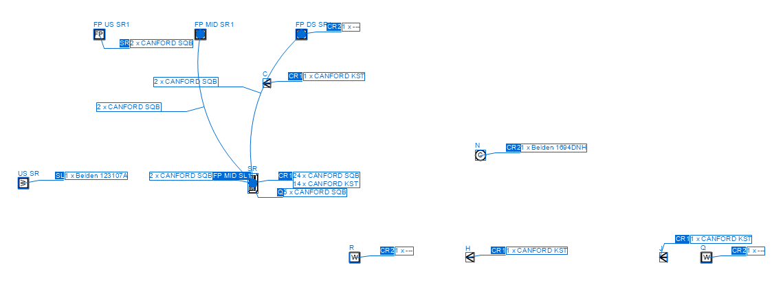
 Creating a cabling sheet
|
Command |
Path |
|
Create Cabling Sheet |
ConnectCAD > Documentation |
The cabling sheet is a view of the floor plan with a summary of the paths used by schematic circuits between drop points.

Cabling is indicated with arcs and home runs, with a customizable balance between the two types. Two graphic styles denote the cable runs:
arcs between drop points, usually to indicate short runs, or
home runs to named locations, with tags showing the numbers and types of cables going to a particular destination.
The cable runs are annotated with the quantities and types of cables for each run. Cabling sheets are created automatically as viewports on a sheet layer; see Zichtvensters op presentatielagen creëren. The view can be presented as an overlay on a floor plan viewport.
To create a cabling sheet:
Select the command.
If the cable route has not yet been analyzed with the Analyze Cable Routes command, this analysis occurs automatically to verify the existence of a route for each circuit.
The Create Cabling Sheet dialog box opens.
Click to show/hide the parameters.Click to show/hide the parameters.
|
Parameter |
Description |
|
Design Layer (Source) |
Select the design layer with the cable route network |
|
Sheet Layer (Destination) |
Select the sheet layer where the cabling sheet will be created, or select New Sheet Layer to create a sheet layer |
|
Viewport Name |
A viewport name is provided automatically; edit the name if needed |
|
Cable Annotation Style |
Drag the slider to select the balance between home run indicators and arc indicators. If one of the starting or ending drop points is not visible, a home run annotation is always used for that cable. |
The cabling sheet is created as a viewport on the designated sheet layer. Each drop point has a label with its name. Cabling is indicated with arcs and home runs. The cabling labels are created on the annotation layer of the viewport, where they can be edited.
